Introduction
From the cement rotary kiln clinker comes out normally at about 1400 0C and goes to cooler. The clinker cooler has two equally important objectives;
- To cool the clinker down to 150 0C – 200 0C to make clinker acceptable for downstream transport equipment and cement grinding equipment; and
- To recuperate heat as much as possible to save fuel consumption for clinkerisation.
Though there are many types of coolers for cooling clinker, the state of the art cooler is Grate Cooler / Cross Bar Cooler. As cooling is a heat transmission process, cooling efficiency is greatly dependent on temperature difference between two media here air and clinker. In a cross current cooler the difference in temperature is pronounced at the start of the process and cooling is thereafter slightly faster and more abrupt (air quenching). Due to the fact, the grate coolers in which the clinker is cooled by air forced up vertically through thick clinker bed has become popular in modern large capacity calciner kiln systems. Mechanically as well as operationally the clinker grate cooler may be considered to be the most complex unit in the clinker burning process.
The clinker cooler has a very strong influence on the heat consumption of the entire pyro installation. Heat consumption in making clinker comprises of the following
- Heat of Reaction;
- Heat Loss from Exhaust Gas;
- Surface Loss from preheater;
- Surface Loss from Kiln;
- Cooler Loss; and
- Free Heat in Materials.
Most of the exhaust Gas heat is normally used for the drying of the raw materials and fuels and therefore this heat is not wasted. The surface losses of kiln and preheater can probably be reduced to minimum possible by extensive use of insulating refractory materials in kiln and preheater. Since the specific heat of air at about 1400 0C is a little higher than that of clinker, the cooler loss could be brought down to the surface loss of the cooler, 7 to 10 kCal / kG clinker; if the amount of cooling air from the cooler is over 1.0 kG air / kG of clinker (almost same as required combustion air quantity) if ideal heat exchange conditions were provided. The cooler thus offers a great potential for improving the overall heat economy of a kiln installation.
In the course of the rapid cooler development in recent years, new generations of grate coolers have come onto the market. In fact, it has meanwhile become difficult to keep track of the current cooler generation however, no great improvements have been made with regard to cooler efficiency and the cooling principle. At the same time, the grate load has typically been increased from approximately 40 to 50 tpd clinker per m2 considering the same clinker temperature though widely accepted value is ~45.
Cooler Sizing Vis A Vis Operation
Normally, the grate coolers are designed considering an operating cooling air flow of 2.2 – 2.4 kG (1.8 – 1.9 Nm3) / kG clinker to achieve clinker temperature of 65 0C above ambient, at the cooler outlet. However, in many plants, especially at a lower production level than rated, the operating cooling air quantity is found to be on much higher side.
The minimum operating cooling air quantity can be achieved by proper cooler optimization which is an art. With proper cooler optimization during operation stage, the followings can be achieved
- Maximum possible secondary and tertiary air temperatures by using little more than 1 kG Air / kG clinker, required for combustion, in recuperation zone where the clinker remains as red. Placement of observation doors on either side wall and on roof at right points, are found to be very useful during optimization stage;
- Minimum cooler exhaust air quantity at around 300 0C.
- Clinker temperature of 65 0C over ambient temperature at the cooler outlet by using total cooling air quantity of ~ 2.2 – 2.4 kG Air / kG clinker, or even lower.
Cooler optimization can be carried out by maintaining
- Maximum possible clinker residence time in the cooler to achieve the best possible distribution of clinker and cooling air. The clinker retention time in the cooler is determined by the grate surface loading and clinker bed depth ;
- Proper cooling air flow distribution;
- Proper tuned PID controller (Grate speed vis – a vis under grate pressure) plays an important role.
Plant Up-gradation and Cooler Retrofit
The standard design norms normally followed by most of OEMs are given as under.
Kiln volumetric Load : Max 2.5 for SP kiln and Max 5 tpd / m3 for calciner kiln.
Kiln Burning Zone Thermal Load : 2.8 – 5.5 X 10⁶ kCal / Hr / m2
Preheater Cyclones : Sizes with 60 – 70 mmWG pressure drop at rated throughput
Calciner : Gas residence time 6 – 7 sec (considering petcoke firing)
Preheater ID Fan : With ~ 10 % margin over design clinker capacity.
Clinker Cooler Loading : Normally 42 – 45 and maximum 47 tpd /m2
Cooling air Quantity : 2.2 – 2.4 kG (1.8 – 1.9 Nm3) / kG Clinker plus margin.
In India, due to raw material characteristic and cement manufacturers’ aggressive attitude, kiln volumetric loading goes for calciner kilns, as high as ~ 7.0. When, during later stage, pyro section up-gradation is planned to utilize maximum available capacity of rotary kiln, cyclone preheater and clinker cooler pose major problem. Depending on extent of up-gradation modification of existing cyclones, installation of a new preheater or an additional preheater is considered. Again, a new calciner in case of existing SP system and increase in calciner height in case of existing calciner system is considered, if lay out permits. The preheater ID fan is changed to handle higher gas flow and increased pressure drop across the preheater.
Many a times the Clinker cooler becomes major bottleneck to support capacity up-gradation. Almost all capacity up-gradation projects involve increment in the capacity of existing coolers. Even with some extent of compromise with clinker temperature increase at cooler outlet, extra grate area requirement comes out to ~ 50 – 60 % for upgradation, in existing calciner kiln system. Up-gradation for older SP plants the cooler grate area increment goes to even 150 %. Grate area can be increased only if free area is available within the cooler itself or by extending cooler longitudinally or by both. In most of the cases the existing lay out limits the cooler expansion and thus limits the up-gradation scope. It is always advisable to keep provision in lay out for cooler expansion – by keeping little longer horizontal length for clinker pan conveyor.
Introduction of new fans or changing cooler fans for higher capacity do not become a major problem.
In most of up-gradation projects coolers are retrofitted mainly aiming at
- Better cooler efficiency by reducing the amount of heat in the cooler vent air and decreasing the specific fan drive powers;
- Reduced or no clinker fall through; and
- Easy cooler maintenance.
The range of possible conversion measures comprises of the following.
- Installation of static inlet grates (specific heat consumption of ~ 15 kCal / kG clinker saving is expected);
- Modification of existing grate plates with new generation plates and improved grate seals;
- Installation of new grate drives and grate bearing assemblies;
- Optimization and replacement of fans; and
- Improvement of the cooler control system, e.g.by installing clinker bed height sensors as part of the stroke frequency control loop.
Clinker Cooler Exhaust Gas for WHR Boilers
Typically, the clinker coolers release large amounts of heated air at 250 to 340° C which can effectively be used in WHRS system. The steam turbine based waste heat recovery boilers (WHRB) are placed between the cooler and the de-dusting system. Depending on situations / requirements, various configurations are considered which are shown below. If no modification is made to the cooler and the excess gas is ducted from the cooler exit to the WHRB, then the vent fan should have enough margins to take care of the pressure drop in the heat recovery boiler. If the WHRB is considered later part the vent fan size has to be increased accordingly or booster fans have to be provided.
As shown in Options – 2 & 3, mid taps can be taken from the cooler such that hot gas at 400-450 °C is taken to the WHRB, whereas the rest of the cool gas at 100 -115 °C is sent directly to the ESP. In this case hotter air is available and steam can be generated at higher pressures, improving the efficiency of the Waste heat recovery system. Hence up to 15% more power can be generated for cooler systems with mid tap. The mid tap is positioned after the tertiary air take-off point and dampers are controlled in such a way that pressure is balanced within the clinker cooler. However, in these cases an additional booster fan may be required to pull the gasses from the cooler mid section. Hence this reduces the net power generation from the waste heat recovery system. Part of the hot gases can be utilized for coal drying as shown in Figures Option – 1 & 2
Option – 1 : No Mid Tap
.
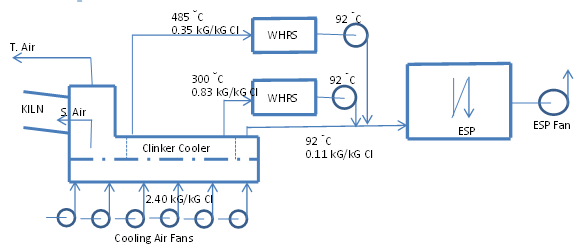
Option – 2 : Single Mid Tap and booster fan
Option – 3 : Two Mid Taps and Booster Fans